| Electrical specifications (initial value) |
LSVH2 Series |
| Products | LSVH2-1100-B**K-CN |
| Number of circuits | 1 circuit |
| Type of output laws | Linear taper |
| Circuit method (Output law) | Potentiometer circuit |
| Total resistance (1-3) | 10kohm (20kohm x2), 5kohm (10kohm x2) |
| Total resistance tolerance | ±20% |
| Absolute linearity (Linear taper) | Within ±5% of the input voltage at each position. |
| Residual voltage (1-2), (2-3) | 20mV or less |
| Residual resistance (1-2), (2-3) | 50ohm or less (Reference values) |
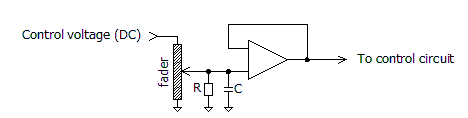
| Touch sense track contact resistance |
30ohm or less (Between terminal T and Control-bar.) |
| Voltage proof | 1 Min. at AC500V |
| Insulation resistance | 50Mohm or more at DC100V |
| Max rating | 0.2W |
| Maximum input voltage | DC30V or less |
| Sliding noise level | 47mV or less (by JIS C 6443) |
| Sliding life | 100,000 Cycles Min. (18cycles/min, Sliding noise level: Less than 100mV) |
| Connector style | B5B-EH (JST) |
| Mechanical specifications (initial value) |
LSVH2 Series |
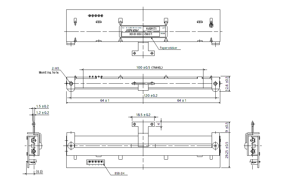
| Travel (Stroke) length | 100mm ±0.5mm |
| Operating force |
0 to 0.1N (Standard) 0.1 to 0.4N (High operating force) |
| Strength Nut-Attached | 100Ncm |
| Attached parts | M3 screw (Length: Panel thickness + 3mm) |
| Stopper strength | 30N |
| Push-pull strength | 30N |
| Alignment to the center | ±0.5mm (State not to pressure control-bar, Measurement position: Mounting surface) |
| General specifications | LSVH2 Series |
| Temperature range | -10 to +70 degrees C (Operating), -15 to +75 degrees C (Storage) |
| Relative humidity | 90%RH (No condensation) |