| ||||| TECHNOLOGICAL INNOVATION ||||| |
 |
1944 The beginning of audio volume controller manufacturing -Start of TKD's attenuator and volume controller- |
| The manufacturing start of the rotary type attenuator ( B and C type etc.)complying to the
BTS standard of Japan Broadcasting Corp./NHK. |
|
 |
1960 The beginning of TKD's SA series volume controller manufacturing -From the rotation type, to the vertical line type - |
| From the rotation type, to the vertical line type attenuator, and to the fader development. |
|
 |
1979 The development of conductive plastic -The birth of TKD's original fader- |
| The manufacturing start of CP, CPA series |
|
 |
1992 The development of motor fader -The automation fader- |
| The manufacturing start of AF, MF series. |
|
 |
2000 The development of fader for the DJ mixer -The new market of fader- |
| The manufacturing start of DJ fader. |
| ||||| TECHNOLOGICAL ADVANCES ||||| |
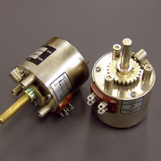
| TOKYO KO-ON DENPA (TKD)began manufacturing the "Profader" over 30 years ago. Due to the high quality and reliability of the TKD range of faders, the Profader is being used by most of the top Professional Audio Companies in the world. They have even referred to, by our Customers, as being "sexy", due to the almost sensual, smooth feel. As well as a full range of manual faders, TKD are producing the largest range of motorized faders available. |
 |
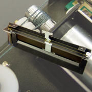
1) Shaft TKD have developed a special 'super-grinding' technology which produces a very accurate component with a superior finish on the surface of the shaft of the "Profader". This technology improves the 'feel' of the Profader. |
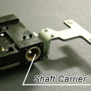 |
2) Shaft Carrier TKD have continually researched materials for the shaft carrier and have developed a special metal-plastic double layer shaft carrier which gives great accuracy in production, improves the 'feel' of the Profader and gives long life in operation. |
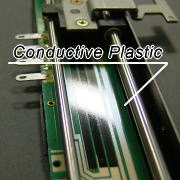 |
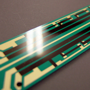
3) Conductive Plastic (CP ) Technology TKD are renowned specialist in CP technology, with a continuing Research & Development programme. The current CP technology has unique qualities in printing and moulding techniques only used on the TKD Profader. By developing a mirror- finish resistance track, peculiar only to TKD's CP technology, the Audio performance of the Profader is superior to other CP technologies and has been highly praised by the major Pro-Audio manufacturers. This technology also produces the superior 'feel' and extended life cycle. |
 |
4) Slider (Brush) TKD have developed a high quality multi-fingered brush, using a combination of materials, which gives exceptional reliability in operation, very low electrical noise and a very smooth 'feel'. The 11 finger brush has been developed in conjunction with the CP technology to produce the soft, smooth feel and a very long life-cycle. |
 |
5) Assembly and Production TKD's philosophy in production is "Technology cannot be seen, it must be touched, used and felt" The TKD Engineers are aware that the fader becomes an integral part of the console and is one component which the user must be comfortable with. Therefore their philosophy is built into the fader. TKD continue to develop new products and improve technology where possible. |
| ||||| ATTENUATOR INFORMATION ||||| |
| Distribute a category of the Website notation in a constant rule by the TKD. | |
| Attenuator |
Use a "dB" for a attenuation level. Determines quantity of attenuation level at each angle. |
| Potentiometer |
The product line of the general A, B, C, M, N curve. Because CP600 series and CP2500 series include "the ladder circuit type of the attenuator category,"Because CP600 series and CP2500 series include "the ladder circuit type of the attenuator category," Please be careful about choices. |
| Terminal number same as an attenuator by the potentiometer circuit. |
1: Input, 2: Output, C: COM(GND), please be careful. Potentiometer of other brands "3:Input, 2:Output, 1:COM" , please be careful on exchange. |
| About load of the measurement condition |
Load: High becomes infinite. The attenuation level with the potentiometer form is influenced by a load condition on the output side. The ideal level is infinite. The error with attenuation specifications appears so that load lowers. An error becomes around 5% with load 20 times as large as total resistance value, and the load recommends what I do than 20 times from a judgment that there will be little influence in use. |
| 1) List of categories |
| Website Category | Variable method | Circuit method | Measurement condition | Products |
| Attenuator |
Step variabled (With click or Without click) |
Potentiometer circuit (Unbalanced) |
Load: High | Potentiometer type attenuator Type-C Type-D Type-E Type-HR23 Type-P2500 |
| Load: Specified | Custom order | |||
| Bridged-T circuit (Unbalanced) |
Load: 600ohm | Bridged-T type attenuator Type-C Type-D Type-E Type-HR23 Type-P2500 |
||
| Load: specified | Custom order | |||
| Bridged-H circuit (Balanced) |
Load: 600ohm | Bridged-H type attenuator Type-C Type-D Type-E |
||
| Load: specified | Custom order | |||
| Bridged-HN circuit (Balanced) |
Load: 600ohm | Bridged-HN type attenuator Type-C Type-D |
||
| Load: specified | Custom order | |||
| Ladder circuit (Unbalanced) |
Load: 600ohm | Custom order | ||
| Other circuit | Load: specified | Custom order | ||
| Variabled (With click or Without click) |
Ladder circuit (Unbalanced) |
Load: High | CP600 Series CP2500 Series CP2511 Series |
|
| Potentiometer | Step variabled (With click) |
Linear (Unbalanced) |
- | Custom order |
| Variabled (With click or Without click) |
A, B, C, M, N (Unbalanced) |
- | CP600 Series CP2500 Series |
| 2) The difference of ladder circuit and the potentiometer circuit |
| Measurement condition | Ladder circuit | Potentiometer circuit |
| Circuit diagram |  |
 |
| Variable resistor |
[Resistance value between 1-2] + [Resistance value between 2-C] ≠ Total resistance value Cannot use it as variable resistance. |
[Resistance value between 1-2] + [Resistance value between 2-C] = Total resistance value Can use it as variable resistance. |
| Characteristic kind to produce | The characteristic that followed BTS-50dB decrement specifications or special order. |
Consecutively variable type: A, B, C, M, N The characteristic that followed BTS-50dB decrement specifications or special order. |
| Main use | For signal level adjustment. | For apparatus setting For signal level adjustment |
| Precautions | Connect COM to the GND of the circuit. Do enough examination, tests, and please use it . |
Do enough examination,tests, and please use it. |
| The attention with specifications | There is no specification of the residual resistance. Because it is measured as synthetic resistance with the branch resistance of the ladder circuit, the resistance except the track between output-COM cannot measure the resistance level only for parts of the COM side. Residual resistance cannot estimate quantity of max attenuation at a deserved value from total resistance. As for the track resistance level measured as some residual resistance levels, in the case of the quantity of decrement measurement, it is the value that you may ignore judging from apparatus internal resistance. Display it with a decrement level from the viewpoint of main use. |
It is the same as general specifications and displays it with a resistance level. The interlocking movement deviation assumes it the decrement level notation that followed JIS. |
| Features | A decrement error is rather relatively less to be able to regulate the resistance level
of each point. Can greatly take quantity of cut off. |
There are few specifications differences and other companies for a general circuit. |
| Cannot use it | The circuit which needs the resistance value setting such as the operational amplifier
feedback circuit. Circuit to use without connecting COM to GND. Variable resistance. |
Do not greatly get the quantity of cut off to depend on the residual resistance (consecutively variable type). |
| 3) The circuit which is used in an attenuator |
| Operate | Circuit diagram | Circuit name | Products |
| Fixed |  |
T circuit | - |
 |
H circuit | - | |
 |
Equilibrium state H circuit | - | |
 |
π circuit | Fixed attenuator series PAD connector series (Sold only in JP) |
|
 |
O circuit | Fixed attenuator series PAD connector series (Sold only in JP) |
|
 |
Equilibrium state O circuit | - | |
 |
L circuit | - | |
 |
Inverting L circuit | - | |
 |
U circuit | Fixed attenuator series (Sold only in JP) |
|
| Variable | Potentiometer circuit | Type-C Type-D Type-E Type-HR23 Type-P2500 |
|
 |
Bridged-T circuit | Type-C Type-D Type-E |
|
 |
Bridged-H circuit | Type-C Type-D Type-E |
|
 |
Equilibrium state bridged H (HN) circuit | Type-C Type-D |
|
 |
Ladder circuit | - | |
 |
Ladder + potentiometer (LP) circuit | - | |
 |
Variabled T circuit | - | |
 |
Variabled L circuit | - |
| 4) Attenuator calculation |
| Z= impedance, V and W are resistance value, K= Attenuation factor |
| Operate | Circuit diagram | Circuit name | Products |
| Fixed |  |
T circuit |  |
 |
π circuit |  |
|
 |
O circuit |  |
|
 |
L circuit |  |
|
 |
U circuit |  |
|
| Variable |  |
Bridged-T circuit |  |
 |
Bridged-H circuit |  |